PID loops are a central component of modulating boiler control systems with applications ranging from basic steam header pressure control to cascading 3-element drum level control. A modern full-metering combustion controller with draft, FGR, VSD, and O2 trim can have as many as 10 PID loops running at once, with some interacting with each other. Understanding the inner workings of a PID loop and how it should be tuned for each process has become an essential skill for the boiler service technician and control systems design engineer.
The basic form of the PID algorithm is the summation of four calculated terms: Proportional gain (“P”), the integral term (“I”), the derivative term (“D”), and the feedforward (“FF”). These terms are each calculated separately based on input constants and variables, then summed together for the resulting control output (figure 2).
Stated simply, a PID is a control algorithm that compares an expected value (setpoint or SP) to an actual measured value (process variable or PV) and adjusts the control output to keep these two values as close as possible. For example, a steam pressure control PID would have a transmitter measuring the current steam pressure (PV), a constant pressure setting that the boiler is expected to maintain (SP), and a firing rate demand signal to the fuel valve (output). If the measured steam pressure falls below the setpoint, the PID increases the boiler firing rate, and conversely if the measured steam pressure rises higher than the setpoint, the PID will decrease the firing rate demand.
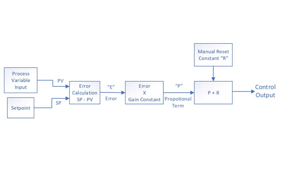
Proportional gain “P”
The proportional gain determines the scale of the PID’s adjustment to the Control Output. It looks at the “error” between the setpoint and process variable and scales this difference by an adjustable gain constant to obtain the “P” term of the PID. A proportional-only controller must have an offset adjustment that determines the output command when there is no SP-PV error.

The proportional controller adjusts the output linearly in either direction from the offset as SP – PV error occurs. In practice, this can lead to difficulty maintaining setpoint as load demands fluctuate and a steady-state offset develops. The proportional controller will need to have its offset manually “reset” to maintain setpoint for the new load. This problem can be corrected by adding the Integral term, also known as the automatic reset (figure 3).
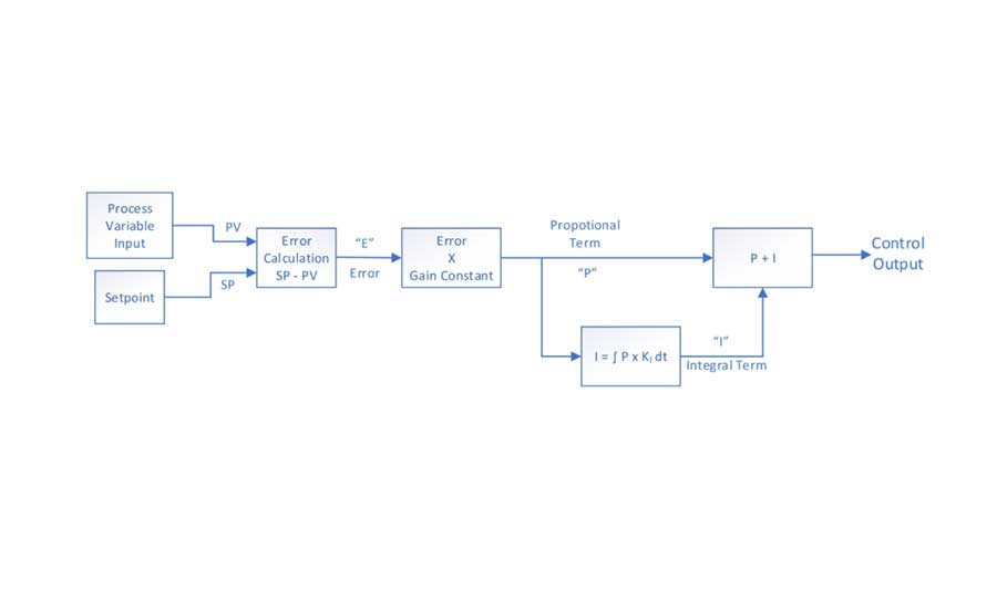
Integral term “I”
The Integral term allows the controller to automatically “reset” the proportional control offset over time to account for changes in load demand. Proportional plus integral (PI) control is the most common form of PID control for boiler applications.
The integral term gets its name from the mathematical function of integration. Integration is the method of calculating the area under a curve by summing smaller and smaller discrete rectangles below the curve. Consider the “P” term discussed above as a fluctuating trend curve graphed over time. The integral term essentially integrates this curve with respect to time to apply a time-averaged reset to the proportional control. The controller cannot re-calculate this integral term in infinitesimally small chunks of time, but instead must account for the time it takes to run a full scan of its software program. The frequency that these rectangle chunks are calculated and added into the PID result is determined by the integral constant KI value.
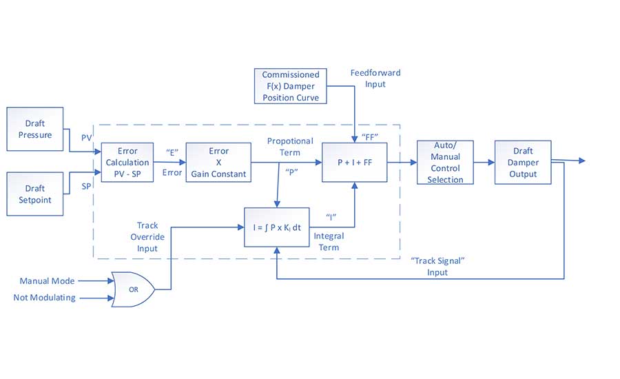
The PID algorithm must also account for integral “windup.” When a control output is placed in manual override, the PID has no effect on changing the output. When this happens, the integral term will continue to add to the PID output command causing “windup.” When the user places the controller back into automatic, the control output will drive to where the PID commands it, which could be a sudden jump. Integral windup can be prevented by forcing the integral to be equal to the track signal (output) minus the proportional term, derivative term, and Feedforward term when the Track Mode Override is enabled. This gives the controller a bumpless transfer from manual to automatic mode.
Derivative term “D”
The derivative term “D” of the PID measures the rate-of-change (dX/dt) of the SP-PV Error and adjusts the PID output accordingly. As the SP-PV error rate-of-change becomes more positive (e.g., the PV is dropping at an increased rate), the derivative term will increasingly add to the PID output. As the error rate-of-change becomes more negative, the derivative term will become increasingly negative and reduce the PID output. The scale of the effect the derivative term has on the output is determined by an adjustable constant KD and the proportional gain constant KP.
The derivative term can alternatively be set up to the negative of the process variable as its “X” term, the dX/dt rate-of-change. As the PV rate-of-change increases and decreases, the derivative term will react inversely.
Reverse acting PIDs
The most common PIDs found in boiler control systems are reverse acting PIDs. In this setup, the control output has a reverse response to changes in the process variable. When the PV increases above setpoint, the output will decrease to maintain the setpoint (figure 4).
There are many other examples of reverse-acting PIDs used in boiler control systems, such as:
- Drum level
- Feedwater pressure
- Full-metered fuel flow
- Full-metered air flow
- Oxygen trim
Direct acting PIDs
Direct acting or forward acting PIDs work in the opposite direction of reverse acting PIDs. In a direct acting PID, the control output increases as the process variable increases. The most common uses of the direct acting PID in boiler controls are for draft control and feedwater pressure when the control output is a feedwater circulation valve (figure 5).
Cascading PIDs
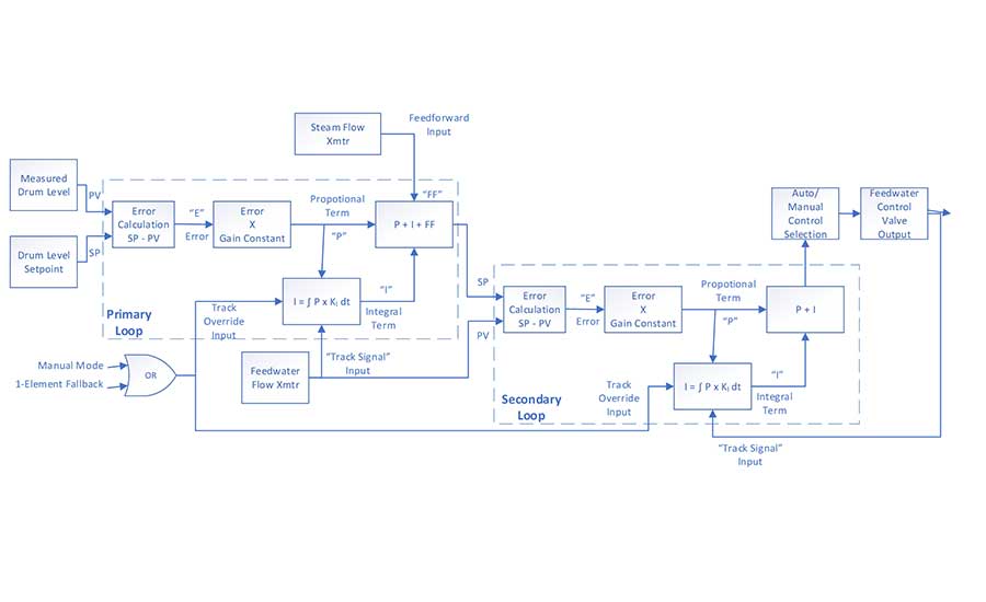
A cascading (or nested) PID loop involves taking the output of one PID and making it the setpoint input of another PID that then sets the control output. In cascading PID control loops, it is necessary for the integral time constant to be set significantly longer in the primary loop than in the secondary loop to reduce loop interaction and increase stability. A common example of a cascading PID loop is 3-Element drum level control where the primary loop uses the drum level, setpoint, and steam flow to determine the feedwater flow setpoint for the secondary loop which in turn controls the feedwater valve output (figure 6).
Overriding PIDs
In an overriding PID configuration, two PID algorithms work in parallel with two separate sets of proportional and integral settings. The choice of which PID output is passed along to the control output is determined by the process overriding conditions. There are a few variations of how an overriding scheme can be set. For example, nuisance high pressure trips on a boiler from overshooting the setpoint can be reduced by having a firing rate cutback override PID.
The cutback PID loop will be set with a higher gain to cause it to react more quickly to setpoint errors. If the primary PID loop is overshooting the setpoint and not dropping the Firing Rate output quickly enough, the higher gain Cutback PID will take over and reduce the firing rate faster. This application can be used in plants that can experience sudden load swings.
Fine-tuning
Let’s get into the process of fine-tuning a PID loop. It is important to remember that in a real-world setting there are many variables that must be accounted for such as the plant process load variations, transmitter calibration and range scaling, control valve stroke, and fuel supply pressures. These can all influence the gain and integral settings required for a PID control loop that is both responsive and stable. The tips presented here should be taken as a starting point only, with the expectation to fine-tune each specific loop in its real-world setting.
Tip 1: When setting gain and Integral constants, it is important to consider the timescale of the process being controlled. A change to the control valve output of a gas flow control PID will see an almost immediate change to the Process Variable. This PID loop will need a lower gain and higher integral setting (or higher proportional band, lower repeats/minute).
An opposite example would be a boiler steam pressure PID control loop, where there will be a delayed change in the steam pressure process variable for a change in firing rate output. This system would typically need a higher gain and a lower Integral to account for the longer time-constant of the system.
Tip 2: A larger calibration range on the transmitter measuring the process variable will require a higher gain setting.
Transmitter spans should typically be set so that the operating setpoint is near the midway point of the transmitter span. For example, if a boiler’s normal operating pressure setpoint is 95 psi, a steam pressure transmitter with a range of 0-200 psi would be a good choice.
In a system where a transmitter is over-spanned, for example 0-500 psi, a 1.0% error would correspond to a 5 psi error from setpoint. For a transmitter with a span of 0-200 psi, a 1.0% error would correspond to a 2 psi error.
Tip 3: A shorter span of a control valve/damper will require a lower gain setting in the PID.
Opposite of tip two above, an over-sized control valve or damper will typically require lower gain and integral PID settings. For example, a drum level control system where the feedwater valve is oversized may supply the full required feedwater flow with the valve only 50% open. In this case a small change to the control valve position will result in a relatively large change in the feedwater flow Process Variable than a properly sized valve would.
Tip 4: Cascading PIDs with similar gain and integral settings will interact with each other and cause loop instability.
When using a cascading PID such as 3-element drum level control, the primary loop (level PID) should have a relatively higher gain and lower integral setting, and the secondary loop (feedwater flow PID) should have a relatively lower gain and higher integral setting.
Tip 5: An input filter can help with “noisy” process variable inputs but should be kept as small as practically possible.
A time-averaged filter on the process variable input will reduce the fluctuations in noisier analog signals like draft pressure and air flow but take caution to not set this too high for PID loops with high integral settings and processes with short time-constants. A time-averaging filter of 2-3 seconds is typically enough.
Tip 6: PIDs assume that control outputs are linear. A fast-opening valve or a damper that is fully open at 60% output will cause the PID loop to be more difficult to fine-tune.
A word of caution before getting into fine tuning: it is important that the person doing the tuning be fully aware of the plant operation constraints and safety considerations. A newly tuned PID loop should only be left unattended in automatic after it has been observed tracking the process load for a considerable amount of time without issues.
There are two goals of a fine-tuned PID loop: 1) maintaining a process variable at a setpoint with minimal deviation from that setpoint, while 2) remaining stable and without oscillations or output hunting. There is often a tradeoff between these two goals. A quick-reacting PID with higher gain will account for setpoint deviations more quickly but is susceptible to overshooting the setpoint and potentially oscillating. On the other hand, a PID that is too slow will be stable, but the Process will deviate further and take longer to get back to setpoint after a load swing.
Fine-tuning the PID attempts to balance these goals.
First, reduce the integral constant and find a proportional gain that responds to a 10-20% load change with two to three oscillations before settling. This load change is best done from an external controller, such as rapidly decreasing the firing rate of a base-loaded boiler while allowing the boiler being tuned to make up the lost steam production. Other techniques such as a rapid change in setpoint or manually controlling the output at a higher or lower position than is needed can produce this to a lesser extent.
Once the loop has been upset, observe the response of the PID controller. If the process variable has no overshoot and is slow to reach setpoint or never reaches it at all, increase the gain and repeat the tuning procedure. If the Process Variable has a high overshoot and oscillates many times or indefinitely, reduce the Gain setting. Once the optimal proportional gain has been found, reduce it by 5-10% then slowly increase the integral setting while upsetting the system again. As before, if the PV is taking too long to get back to setpoint, increase the integral setting. If the PV oscillates too much, reduce the integral setting.
There are a couple of common issues to look for after a PID loop has been tuned. If there is slightly too much of both proportional gain and Integral at the same time, there can be a continuous and slow oscillation over a long time-period (possibly 5-10 minutes or more). In some cases, this may be acceptable, but it is not a well-tuned PID loop and does not have tight control. Sometime tight control can be achieved while having the control output swing wildly or oscillating. Again, this may be acceptable in some cases, but it could lead to a shortened lifespan of an actuator or control valve. This can be minimized by reducing gain but will result in a wider PV deviation from setpoint.
This article has covered many of the basic elements of PID loops as well as a number of tips for fine-tuning them. While every tip may not be relevant to your situation, the information and tips above should help you to better understand the inner workings of a PID loop and how they can be tuned according to your needs.
If you are interested in more educational information like this, Preferred Utilities offers regular webinars on topics ranging from fuel oil system design to safety practices and winterization techniques.