Over the past several years, I’ve worked in several high-rise condominiums that utilize a makeup air unit (MAU) that conditions 100% outdoor air to a neutral dry bulb temperature (~70°F) and suitable dew point (<57°). The MAU ducts adequate ventilation air directly into the individual condos. It also keeps building pressure slightly positive. Temperature control at the individual units is achieved with terminal devices, often through hot water finned-tube radiation and chilled water fan coil units (FCUs).
To achieve adequate dew point control in the MAU supply air during humid Minnesota summers, the chilled water cooling coil is typically placed upstream of the heating coil within the MAU. This arrangement subcools the air to wring out the moisture, then reheats it to 70° supply air temperature set point.
These buildings also often have large window-to-wall ratios. The excessive amounts of glazing at times results in some units requiring cooling from the chilled water FCUs during very cold (<20°) but sunny outdoor air conditions. Therefore, the chilled water system needs to remain enabled even during cold winter conditions.
Each article in this three-part series details a case study. Each case study looks at different high-rise condominiums, and all three buildings have slightly different system configurations. All three buildings had an existing strategy to provide wintertime chilled water system operation. In each instance, I was working on other systems in the building when inadequacies in the existing wintertime chilled water system strategies were brought to my attention. These issues were addressed in slightly different manners, but all took advantage of the cooling coil’s position upstream of the heating coil within the MAU. The cooling coil was essentially used as a dry cooler. There were certainly several “Aha!” moments along the way, which these articles seek to explain.
Building No. 1
The first building utilized a chilled water system in which the air-cooled chiller remained enabled until the ambient temperature dropped below 25°. The chiller was not designed for such low ambient operation, which caused a litany of issues. In fact, three of its six compressors were failed at the time of my initial investigation. Additionally, several residents were vocal that they needed cooling at outdoor air conditions below the 25° cutoff. Not only was this strategy damaging the chiller, but it was also not meeting the needs of building.
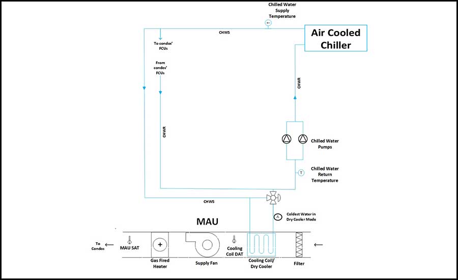
The building also had a MAU with the chilled water cooling coil upstream of a gas-fired heater. The chilled water coil was served by a three-way control valve and the chilled water system operated with a 35% ethylene glycol concentration (see Figure 1).
Improved sequence of operation
To provide chilled water during even colder than 25° ambient conditions, as well as to alleviate the need to force chiller operation at such conditions, we opted to implement a strategy that utilized the chilled water coil as a dry cooler during low ambient conditions. The sequence was as follows:
System enable:
- When outdoor air temperature was above chiller mode enable set point (40°, adj), the chilled water system was in chiller mode. When outdoor air temperature dropped below chiller mode enable set point, the chilled water system was in dry cooler mode. If outdoor air temperature dropped below system disable set point (10°, adj,), the chilled water system was in disabled mode.
- The lead chilled water pump operated in chiller mode, dry cooler mode, and for the first 30 minutes after entering disabled mode.
In chiller mode:
- The chiller was enabled and controlled to a chilled water supply temperature set point (44°, adj.).
- The MAU chilled water coil’s control valve controlled as follows:
- When ambient dew point was below 57°, the valve modulated to maintain MAU supply air temperature at its set point of 70°.
- When ambient dew point was greater than 57°, the valve modulated to maintain cooling coil discharge air temperature (DAT) at 57° (adj.).
- The gas-fire heater operated when this dehumidification mode took precedence to raise supply air temperature back to ~70°.
In dry cooler mode:
- The chiller was disabled, but chilled water was allowed to circulate through it as this was a primary-only hydronic system (i.e., the water needed a path to flow through).
- The MAU’s chilled water coil’s control valve modulated to maintain chilled water return temperature at 44°.
In disabled mode
- The chiller remained disabled.
- The MAU’s chilled water coil’s control valve closed to the coil.
Lessons learned
- This strategy lessons the load on the downstream gas-fired heater during dry cooler mode, as the chilled water is rejecting heat into the MAU air stream in such instances.
- A high enough concentration of glycol is needed to maintain the freeze point below the lowest temperature in which the system would operate at (i.e., the water at location A of Figure 1 could be moving at temperatures as low as the system disable set point). Looking at burst point temperature alone will not suffice if you want to ensure you are not pumping ice slush around the building.
- The chilled water return temperature (CHWRT) sensor was utilized as the controlling sensor in dry cooler mode in lieu of the chilled water supply temperature (CHWST) sensor for three reasons.
- Both temperatures should be about equal in this mode, as chilled water is just passing through the chiller, not intentionally being cooled down by it. Admittedly, some cooling is probably occurring just by the fact the air-cooled chiller is located outside.
- The CHWRT sensor was already wired to the MAU controller. This allowed for the control loop, which modulates the cooling valve to maintain CHWRT at set point, to not relay on passing information over the building automation system (BAS) network, which can create controllability issues when the network buffers.
- The CHWRT sensor was physically located much closer to the MAU than the CHWST sensor. Minimizing the distance reduced the system time constant and thus improved our ability to tune the control loop.
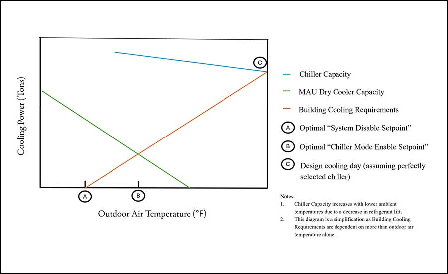
- Making the chiller mode enable set point and system disable set point adjustable on the BAS’s graphic allowed for the building engineer to zero in on the optimal bookends for dry cooler mode operation. The issue with implementing dry cooler mode is that as outdoor air temperature rises, building cooling requirements rise, but cooling capacity of the dry cooler decreases (see Figure 2 for a very simple diagram depicting this). This means that having too high of a chiller mode enable set point could result in the building’s cooling requirements not being met during milder ambient temperatures as the dry cooler has insufficient capacity. Thus, the building operator would gradually raise the chiller mode enable set point in the shoulder seasons, and the system disable set point in the winter, until he got lack-of-cooling complaints from residents. He would then drop the respective set point down a few degrees and call it good. This ensured the chiller mode enable set point was at an appropriate temperature to ensure building cooling requirements are consistently met, and the system disable set point was at the correct value to prevent running the system when it was no longer needed.
- We ended up having to lower the cooling coil DAT set point used for dehumidification from 57° down to 55°. This slight drop allowed for the gas fired heater to stably control to a supply air temperature of 70° without cycling on and off at low fire.
Conclusion
This is the first of three articles on the application of MAU cooling coils as dry coolers. The next two articles will detail two additional buildings, both of which utilize a water-cooled chiller, a 100% water chilled water system, and a glycol chilled water loop dedicated to the MAU cooling coil. There were plenty of other aha moments experienced with those systems as well. The intent of these three case studies is to inspire some creativity in the solutions you are providing to your clients.