The previous article introduced the concept of using a chilled-water cooling coil, located upstream of a heating coil within a makeup air unit (MAU), as a dry cooler. This allows for more efficient and stable operation of a chilled water system at lower ambient air temperatures. A case study was presented for a high-rise condominium, which required chilled water during ambient temperatures down to 10°F. This article and the next will present two more case studies on systems with similar arrangements but slight differences that presented various challenges and opportunities.
Building No. 2
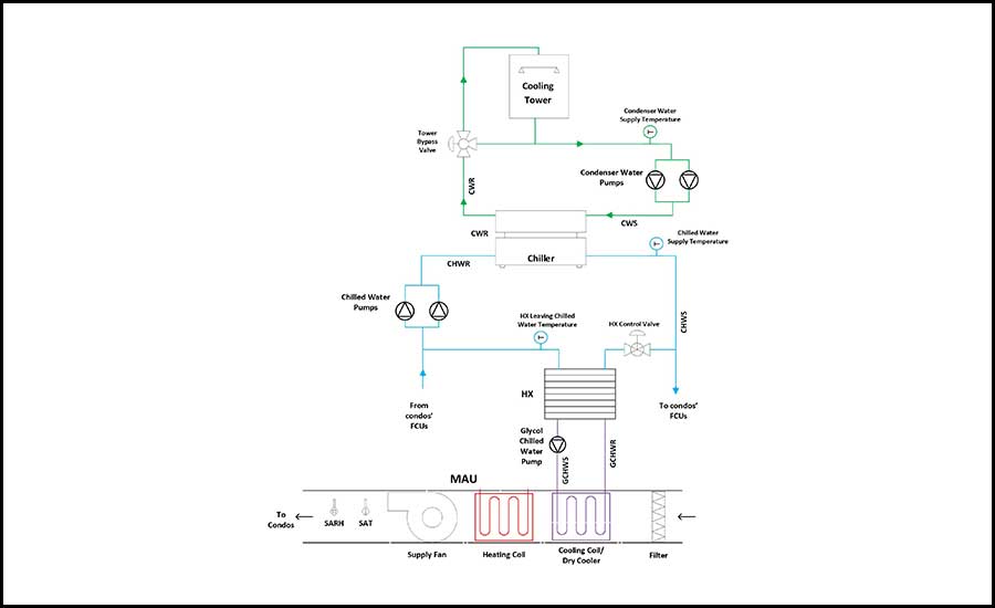
The second case study in this series had a system configuration depicted in Figure 1. The condenser water system had heat trace on the outdoor piping as well as a basin heater in the cooling tower. This allowed for shoulder season operation, but the system certainly was not designed for Minnesota winter conditions. Therefore, it was drained in early November each year.
The chilled water system does not contain glycol. The only portion of the system that would be exposed to freezing temperatures would be the cooling coil located in the MAU. To protect that coil but avoid the costs of adding glycol to the entire system, a separate glycol chilled water loop is present. This glycol loop is dedicated to the MAU cooling coil and is served by the chilled water system via a plate and frame heat exchanger (HX).
While working in the building on a completely separate system, the building engineer pointed out the chilled water supply temperature was operating around 70°F despite a wintertime chilled water sequence which utilized the MAU’s chilled water cooling coil as a dry cooler, being active. That existing, wintertime chilled water sequence opened the HX control valve on the chilled water side wide open and ran the glycol chilled water pump when the cooling tower was seasonally drained, and the chiller was not available. As outdoor air temperatures were in the low 20s during my initial investigation, the performance of this wintertime chilled water sequence was clearly suspect. It was realized that the chilled water (100% water) within the HX had frozen, obstructing any flow, and thus preventing any cooling.
Improved sequence of operation
After disabling the glycol chilled water pump, allowing the system to thaw, and verifying the HX was not compromised, we needed to rethink the existing sequence. We landed with the following:
System operating mode:
- A software switch for winter or summer operation was placed on the BAS graphic screen. It was to be toggled by the building engineer when the condenser water system was drained in the fall or filled in the spring.
- During summer operation, when outdoor air temperatures were above chiller mode enable set point (40°F, adj), the chilled water system was in chiller mode. When outdoor air temperatures were below chiller mode enable set point, the chilled water system was in dry cooler mode.
- During winter operation, the system remained in dry cooler mode unless the outdoor air temperature dropped below system disable set point (10°, adj,), in which case the chilled water system entered disabled mode. A control differential of 8° (adj), was added to the system disable set point. For example, the system enters disabled mode when outdoor air temperature drops below 10°, but doesn’t reenable dry cooler mode until the outdoor air temperature rises above 18°.
- The lead chilled water pump operates in chiller mode, dry cooler mode, and for the first six hours of disabled mode.
Chiller mode:
- The lead, constant-speed condenser water pump was enabled.
- The cooling tower’s fan and bypass control valve worked to maintain condenser water supply (CWS) temperature at its set point. That set point was reset off ambient wet bulb temperature.
- The chiller was enabled and controlled to maintain the chilled water supply (CHWS) temperature at its set point. That set point was reset off outdoor air temperature.
- The constant speed glycol chilled water pump ran continuously.
- The HX control valve received the more open command of the following two control loops:
- Maintain MAU supply air temperature at its set point of 70°.
- Maintain MAU supply air dewpoint at its set point of 57°.
- The hot water reheat coil was allowed to operate when this dehumidification control loop took precedence to raise supply air temperature back to ~70°.
Dry cooler mode:
- The chiller, cooling tower, and condenser water pump were disabled, but chilled water was allowed to circulate through the chiller, as this was a primary-only hydronic system (i.e., the water needed a path to flow through).
- The HX chilled water control valve was commanded 100% open.
- The HX leaving chilled water temperature (LCHWT) was monitored (see Figure 1). If it dropped below set point (38°, adj.), the glycol pump was disabled. If LCHWT rose a differential (10°, adj) above set point, the glycol pump reenabled.
Disabled mode
- The chiller, cooling tower, and condenser water pump remained disabled.
- The HX chilled water control valve remained 100% open.
- The glycol chilled water pump was disabled.
Lessons learned
Here are a few of the things I took note of:
- The automated transition between chiller mode and dry cooler mode during summer operation (i.e., cooling towers not drained) alleviated the previous burden placed on the building engineer to manually place the unit into dry cooler mode every time the ambient temperature dropped too low to run the chiller during the shoulder seasons.
- To promote stable operation of the chiller during lower ambient conditions while in summer mode, we needed to implement aggressive condenser water and chilled water supply temperature set point resets. This minimized cycling of the chiller and avoided a surge.
- We do not control to CHWST set point in dry cooler mode. We just get what we get. However, we do cycle the glycol pump off when the HX LCHWT drops too low and freezing becomes a risk. Water at that location is the coldest in the system.
- Disabled mode was never implemented prior to this intervention. We can only assume seasonal freezing of the water within the HX occurred every year up until this point.
- When entering disabled mode, we needed to keep the lead chilled water pump on for six hours to ensure stagnant glycol in the HX was adequately heated prior to stopping chilled water flowing through the HX. Additionally, the HX control valve remained wide open during disabled mode as an added safety measure. If freezing did occur, pressure could be relieved from both ends of the HX.
- The chiller manufacturer was consulted to ensure passing chilled water through a non-operational chiller didn’t create any unintended issues for the chiller. I don’t know what such unintended issues might be, but I didn’t want to be responsible for damaging a recently installed chiller.
- The LCHWT set point and associated control differential, which enables and disables the glycol chilled water pump during dry cooler mode, were made adjustable. Through trial and error with those two settings, we found a relatively large differential was needed (~10°) for stable operation to prevent short cycling of the glycol chilled water pump.
- There was also a need for a sizable differential between when the system entered disabled mode and when it came out of it, for two reasons:
- During disabled mode, the temperature of the stagnant glycol within the MAU coil approached ambient conditions. To prevent dangerously overcooling the chilled water immediately, which would result in short cycling of the glycol chilled water pump, we allowed the ambient temperature to rise a bit more before reenabling Dry Cooler Mode.
- We have also seen firsthand in this building that cooling requirements are a function of ambient temperature and solar gains, but thermal mass of the building plays a large role as well. If all other variables were kept constant, we have seen much smaller cooling demand from the building at a given ambient temperature when that ambient temperature is rising after a cold snap, as opposed to when the ambient temperature is dropping after a period of warmer weather.
Conclusion
This is the second of three articles which explores utilizing a MAU cooling coil as a dry cooler. The final installment will look at another system with a water-cooled chiller. That system looks very similar to the one discussed in this article; however it includes a variable-speed glycol chilled water pump, which provides added modulation capability for the wintertime sequence of operation.