Chiller plant control optimization has achieved heightened popularity over time as computerized controls enable increasingly sophisticated algorithms to maximize plant efficiency. In a predicted backlash to the “black box” nature of proprietary optimization packages, engineers have developed simplified controls strategies that approximate optimization without the cost and complexity of a package. These strategies grew out of a need to prevent plant operators from switching to operating their plants manually when the causes of inadequate plant performance, accidental chiller shutdown, excessive cycling, or any of a number of problems could not easily be diagnosed.
In parallel, the push for maximizing plant efficiency has led to the adoption of code requirements for air- and water-side economizers. Economizers, though beneficial, add complexity that may undermine the goal of simplifying plant controls. This article examines water-side economizer control as well as plant optimization controls strategies with respect to water-side economizers.
Simplified Optimization Strategies
The system under consideration is a water-cooled chiller plant with cooling towers, condenser water pumps, centrifugal chillers, distribution pumps, and a water-side economizer heat exchanger (Figure 1). The chillers are arranged in parallel. Distribution pumps operate in a variable-primary arrangement. Per ASHRAE Standard 90.1’s prescriptive requirements, the heat exchanger is located upstream of the chillers and in series with them.
Typical simplified optimization strategies for controlling each component include the following.
-
Locate temperature sensors at the inlet and outlet of the parallel chiller arrangement. The chillers energize or de-energize in response to increasing or decreasing chilled water temperature returning from the system. A differential pressure measurement across the evaporator can be used to estimate chiller flow based on the manufacturer’s performance data. Alternatively, a flow meter located at the outlet of each evaporator would provide a more accurate output. Flow meters may also be used to prove minimum flow before chillers are staged on or alarm low-flow conditions at the evaporator. Selection of a high-quality, accurate flow meter without the need for frequent recalibration is critical to plant performance.
-
The BMS calculates chiller output in Btuh using measured temperatures and flow at the chillers, which are variable speed and follow a staging algorithm programmed into the BMS written to minimize chiller kW/ton and prevent excessive cycling. A significant contribution of optimization packages has been used to demonstrate the plant efficiency of multiple chillers running at part load may exceed that of a single chiller running at near full load. In the absence of an optimization package, manufacturer data may be used to compare the efficiencies of single chillers and chillers operating in parallel to write chiller staging rules for any given plant.
FIGURE 1.
-
A best practice for the distribution pump control includes VFDs responsive to differential pressure transmitters in hydraulically remote locations. Even when in parallel, pumps are often assigned to a chiller and staged with that respective chiller. A wire-to-water analysis shows that multiple pumps operating at part load can operate at higher efficiencies than a single pump at near full load, which is also the case with chillers. Simply staging the pumps with the chillers may achieve these higher efficiencies if the chillers follow optimized part-load staging rules. This strategy can be verified with pump manufacturer data.
-
Modeling has demonstrated that in most climates, the chilled water system sees limited energy savings when condenser water pumps operate on VFDs. Larger efficiency gains are achieved when designing the condenser water system for 1.6-2.3 gpm/ton per the ASHRAE GreenGuide. There is more to be gained on the design side than in controls when it comes to condenser water pumps. Constant volume condenser water pumps with three-way valves at the condenser are a sensible strategy even for plant optimization.
-
Cooling tower fans should include VFDs and do not require a complex controls package for optimization. Modeling shows that in many conditions, controlling fan speed to the condenser water return temperature set point instead of the supply will achieve a highly efficient tower performance.
-
Staging of cooling towers should be optimized by operating the maximum number of towers possible while complying with the manufacturer’s minimum flow requirements. Low-flow accessories, such as nozzles or dams, can significantly reduce the minimum flow requirement and allow additional towers to run, so they should always be specified.
Meticulous Maintenance
After a plant optimized control strategy has been implemented, the challenge shifts to maintaining that high level of performance. When mechanical systems issues occur, full-time operations staff members are expected to fix any problems as soon as possible, which often results in equipment being placed into hand mode. Unfortunately, equipment placed into hand mode will often remain in hand mode for extended periods of time, which results in temperature control issues and excessive energy consumption.
Ensuring that hand mode is used as a short-term fix rather than a long-term operational strategy is important in ensuring the savings from an optimized control sequence are realized. Two simple, low-cost strategies can be implemented:
-
Provide hand mode alarms: Most VFDs and control panels for major equipment, including chillers and boilers, will be equipped with BACNET connectivity through either MS/TP (RS-485 cable) or Ethernet/IP (CAT cable). Hand mode status is typically a standard BAS input through the BACNET connection, meaning that the data is already available for most systems and requires only that the controls vendor programs the BAS to monitor the hand mode status input to generate an alarm.
-
Provide a release from “hand mode” virtual button: The controls provider can program a virtual button, which will initiate an orderly shutdown and startup upon which all equipment will be released from hand mode.
Economizer Control
The partial water-side economizer mode should be initiated based on the outside air wet bulb temperature, chilled water return temperature, and calculated values for a predicted heat exchanger and cooling tower approach. The outside air wet bulb temperature is typically a calculated value using inputs from temperature and humidity sensors. A high-quality humidity sensor must be provided and maintained throughout the life of the building, or issues, including excess fan energy and frequent changeover from economizer mode to normal mode, will occur.
During partial economizer mode, tower fans should be operated at full speed to provide as low of an approach as possible. Condenser water flow through the heat exchanger should be equal to the design flow (constant volume) or reduced as required to ensure a minimum DeltaΔT to avoid wasting pump and cooling tower fan energy.
When the leaving chilled water temperature from the heat exchanger becomes equal to the chilled water supply temperature set point, the chillers are disabled and the cooling tower fan speed is modulated to maintain the chilled water temperature. The economizer mode should be disabled altogether when the heat exchanger is no longer capable of reducing the chilled water return temperature by a specified amount (typically 1°-2°F).
ASHRAE Standard 90.1-2016 requires cooling towers to be sized so that the water-side economizer system is capable of meeting 100 percent of the cooling load at outdoor conditions of 50°DB and 45°WB. A mode of operation for partial economizer mode in which both the heat exchanger and chillers are operated simultaneously must be provided. Chilled water temperature reset controls will maximize the number of hours the economizer mode can be used.
FIGURE 2.
Selecting cooling coils expected to operate during colder months for higher-than-designed entering chilled water temperatures will allow a more aggressive chilled water reset, resulting in more economizer hours. Allowing increased coil flow and a reduced waterside Delta T in economizer mode can help keep air-side pressure drop low for these coils. When selecting coils based on economizer mode temperatures, rerating the coils for design day conditions and considering their impact on the system is a must. It’s important for engineers to document both the economizer design condition and the summer design condition to ensure the expected performance is realized and that when used, pressure independent and auto-flow valves are sized based on the higher flow rate.
Another water-side economizer control strategy incorporates air-side economizers, which are often viewed as an all-or-nothing approach. However, using a partial air-side economizer can facilitate an aggressive supply air temperature reset with little increase in first cost in some scenarios for air handlers serving zones with high sensible or total cooling loads in the winter or shoulder season. Increasingly sophisticated demand-controlled ventilation strategies, such as those detailed in ASHRAE Guideline 36, result in dedicated outside AHUs and fans operating at part loads. As a result, the outside air volume to the critical AHUs driving the chilled water temperature reset sequence can be increased beyond the typical maximum outside air set point in order to reduce the load on the cooling coil and allow the chilled water temperature to reset higher. The only increase in first cost required to implement this sequence is larger outside air ductwork to the air handler intake, a larger flow control device from the outside air source to each AHU, and a slightly more complex sequence of operation.
Operating the system in economizer mode as often as possible will result in the highest energy savings; however, one potential issue to consider is chiller refrigerant differential pressure. Cold entering condenser water temperatures will cause the differential pressure of refrigerant in the condenser and evaporator to drop. Modern chillers are typically capable of operating below their minimum pressure differential for a short period of time prior to tripping. These capabilities often vary between manufacturers and should be considered while writing specifications and throughout the bidding process. Two strategies can be used to bring refrigerant pressure differentials into line quickly prior to a chiller tripping:
-
Condenser water flow can be reduced. This step will result in a higher condenser water Delta T and increased refrigerant pressure. Specifying a modulating control valve to perform both head pressure control and shut-off duty is a relatively low-cost method to reduce flow. When throttling, the valve should be controlled using a cascading control loop and the input from the chiller’s condenser water flow-sensing device to allow for more stable control and the use of a line size butterfly valve.
-
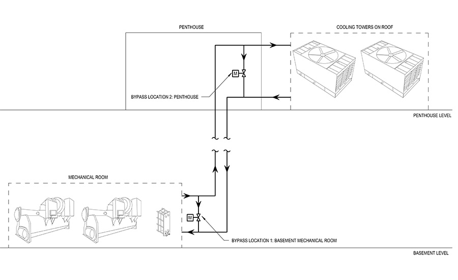
System volume can be reduced using by-pass valves. Should an issue with the first strategy occur, a chiller trip can be avoided by quickly raising the condenser water loop temperature. The speed at which the loop temperature can be raised is a function of the load and effective system volume. Consider a 1,200-ton chilled water plant with cooling towers on the roof and chillers in a basement mechanical room with 16-inch condenser water supply and return piping. This system is depicted in Figure 2. Three potential bypass locations are shown: in the basement, the penthouse, and directly to the tower basin.
The overall system volume was calculated to be 3,400 gallons. The time required to warm this loop from an initial temperature to a final temperature can be calculated using the following equation:
Warming loop time = 
Where:
Warming loop time is in minutes
Gallons: System volume
Temperatures: Condenser water in degrees Fahrenheit
Tons: Anticipated heat rejection
The following table summarizes the change in system volume and loop warm-up time based on three different cooling tower bypass locations. Note that the smaller the system volume, the more quickly the loop can be warmed and the more quickly the chiller differential pressure can be brought into line.
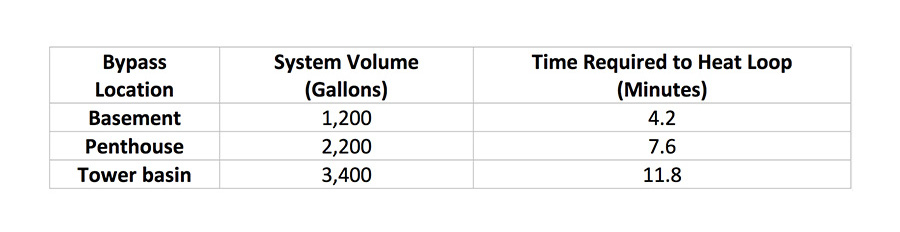
The control sequence should be programmed to modulate the bypass control valve and cooling tower isolation valves for full bypass flow. Once the desired loop temperature has been achieved, the bypass valve can be modulated closed, and the system can resume its typical sequence of operation for non-economizer mode.
Chiller plant optimization strategies and economizer control must be held in balance with the reality that complex controls are implemented differently. These described strategies may help prevent the plant-operating setbacks that arise with complex controls while allowing the plant to operate at higher than typical efficiencies. ES
References
ASHRAE. 2010. ASHRAE GreenGuide: The Design, Construction, and Operation of Sustainable Buildings, 3rd Ed.
Schrecengost, R. 2014. “Designing chilled water systems.” Consulting-Specifying Engineer, September.
Taylor, S. 2012. “Optimizing Design & Control of Chilled Water Plants: Part 5: Optimized Control Sequences.” ASHRAE Journal, June.
Taylor, S. 2014. “How to Design & Control Waterside Economizers.” ASHRAE Journal, July.
Zak, P. 2012. “Control sequences for chilled water systems.” Control Engineering, January.